Difference between revisions of "Agilla 1.x Grid Topology"
(New page: Since TinyOS does not provide geographic routing or location discovery, and a real multi-hop networks would require too much space, Agilla assumes a multi-hop sensor network arranged in an...) |
|||
| Line 4: | Line 4: | ||
[[image:5x5_agilla_network.jpg|center|thumb|350px|A 5x5 Agilla network]] | [[image:5x5_agilla_network.jpg|center|thumb|350px|A 5x5 Agilla network]] | ||
| + | |||
| + | By assuming a grid topology, we corrolate the mote ID with its location as follows: | ||
| + | |||
| + | <pre> | ||
| + | ID = x + (y-1)*(number of columns) | ||
| + | </pre> | ||
| + | |||
| + | Alternatively, given the node ID, its location can be calculated as follows: | ||
| + | |||
| + | <pre> | ||
| + | x = [(ID-1) mod (number of columns)] + 1 | ||
| + | y = (ID – x)/(number of columns) + 1 | ||
| + | </pre> | ||
| + | |||
| + | For example, in a 4x4 network, the nodes would have the following IDs and locations: | ||
| + | [[image:agilla1grid.jpg|center|thumb|425px|A 4x4 Agilla 1.x network and its grid topology]] | ||
Revision as of 19:56, 10 December 2007
Since TinyOS does not provide geographic routing or location discovery, and a real multi-hop networks would require too much space, Agilla assumes a multi-hop sensor network arranged in an n x m grid. A multi-hop network is achieved by modifying TinyOS's network stack to filter out messages from non-neighbors. A node can only communicate with its immediate neighbors as specified by the grid topology. Each node is identified by its integer (x,y) location. The lower-left corner of the network is (1,1) and the x and y coordinates increase going left and up, respectively. The mote connected to the base station is at (0,0). Each node in the grid can communicate with its immediate horizontal, vertical, and diagonal neighbors, for a maximum of 8 neighbors. The base station node can communicate with any node on the first row.
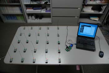
Below is a 5 x 5 network:
By assuming a grid topology, we corrolate the mote ID with its location as follows:
ID = x + (y-1)*(number of columns)
Alternatively, given the node ID, its location can be calculated as follows:
x = [(ID-1) mod (number of columns)] + 1
y = (ID – x)/(number of columns) + 1
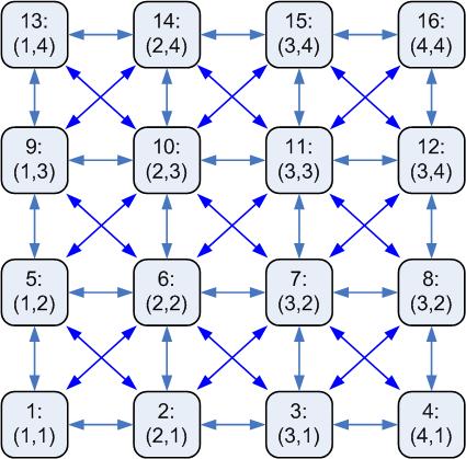
For example, in a 4x4 network, the nodes would have the following IDs and locations:

